To Route Duct Bank
The
Duct
Bank Router enables you to interactively route duct bank in your current
design file.
- Select Duct Bank Router from the Underground System ribbon.
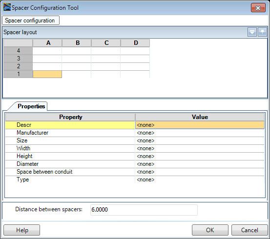
- Click the Duct bank configuration icon to setup the configuration for the duct bank.
- In the Spacer Configuration tool there is a Spacer layout grid at the top of the dialog. This represents the current layout of the duct bank.
- Click the Spacer Configuration option and click Setup Grid from the drop down section.
- In the Setup Grid dialog, set the number or Rows and Columns to 4.
- The Starting row/column designators can also be changed if desired, but do not affect the layout. This is used to identify cells (such as 1A, 1B etc.)
- Click OK to return to the Spacer Configuration Tool.
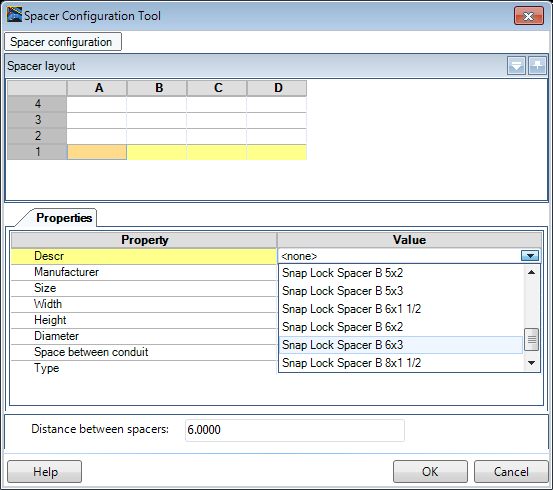
- Select the bottom row and select the Snap Lock Spacer B 6x3 from the drop down list.
- Spacers on the bottom row must be defined first as all other spacers are stacked on top of those base spacers. Note the spacer size is prefaced with a B designating it is a base spacer.
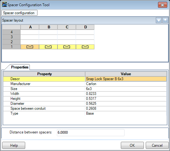
- The spacer image is displayed in the cells selected and the spacer properties fields are filled in with the information of the selected spacer.
- Once the base spacers are defined, define the spacer type for the row above that one. You will notice the Spacer selection only contains spacers of the same size as the base and the size is prefaced with a I designating it as an intermediate spacer.
-
Optional: Additional Rows or Columns can be
added to the layout by right clicking in a Row/Column header and selecting Add
from the context menu.
- To save the configuration, click the Spacer Configuration tab and enter a name into the Configuration field. Click Save.
-
Optional: Click the
Preview icon to view how the duct bank layout
will display.
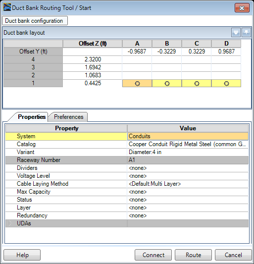
- Click OK to return to the Duct Bank Router.
- Select the bottom row in the Duct bank layout section and select Conduits as the System.
- Select a Catalog from the list and define a size from the Variant list such as 4 in.
- All other properties are optional and can be changed after the duct bank is placed using the Duct Bank Properties tool.
- Switch to Preferences tab. In this section you can define a bend radius for standard bends as well as determine how non-standard bends will be handled in the routing process.
- Return to the Properties tab and define conduit size and properties for the remaining duct bank rows.
- Optional: Once a duct bank configuration is complete it can be saved for future use. Type in configuration name then use option Save to save it. All users that are working on the same project will be able to use this saved configuration.
- Press Route.
- To start the duct bank placement at correct elevation, use snap and offset AccuDraw functions to place the duct bank in reference to other components.
- For example, to place a duct bank 25 feet away from the existing raceway, make point of origin at the existing raceway and offset it for - 25 feet in Y direction and 5 ft in Z direction.
- Click a data point to start the duct bank placement.
- Place a 50 ft long section using AccuDraw.
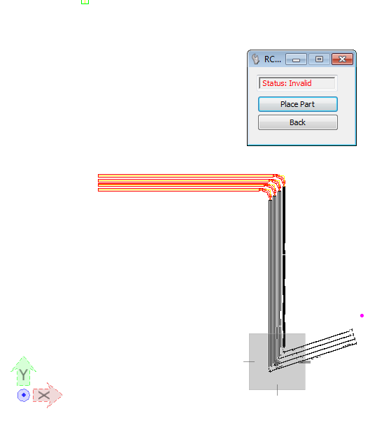
- To make a 90 degrees horizontal bend simply move cursor towards the bottom of the screen and place an additional 25 ft long section.
- When placing a bend, if the angle cannot be made with a custom bend, the Status will be view as Invalid.
- Continue routing using Accudraw.
- After routing the last duct bank section, right-click to end the command.